.webp)
One of the reasons clinching can be such a great method to join sheet metal is that you can test the quality of the joints it creates non-destructively.
Here’s how to visually check your clinch to ensure you’ve created strong, stable joints that will last.
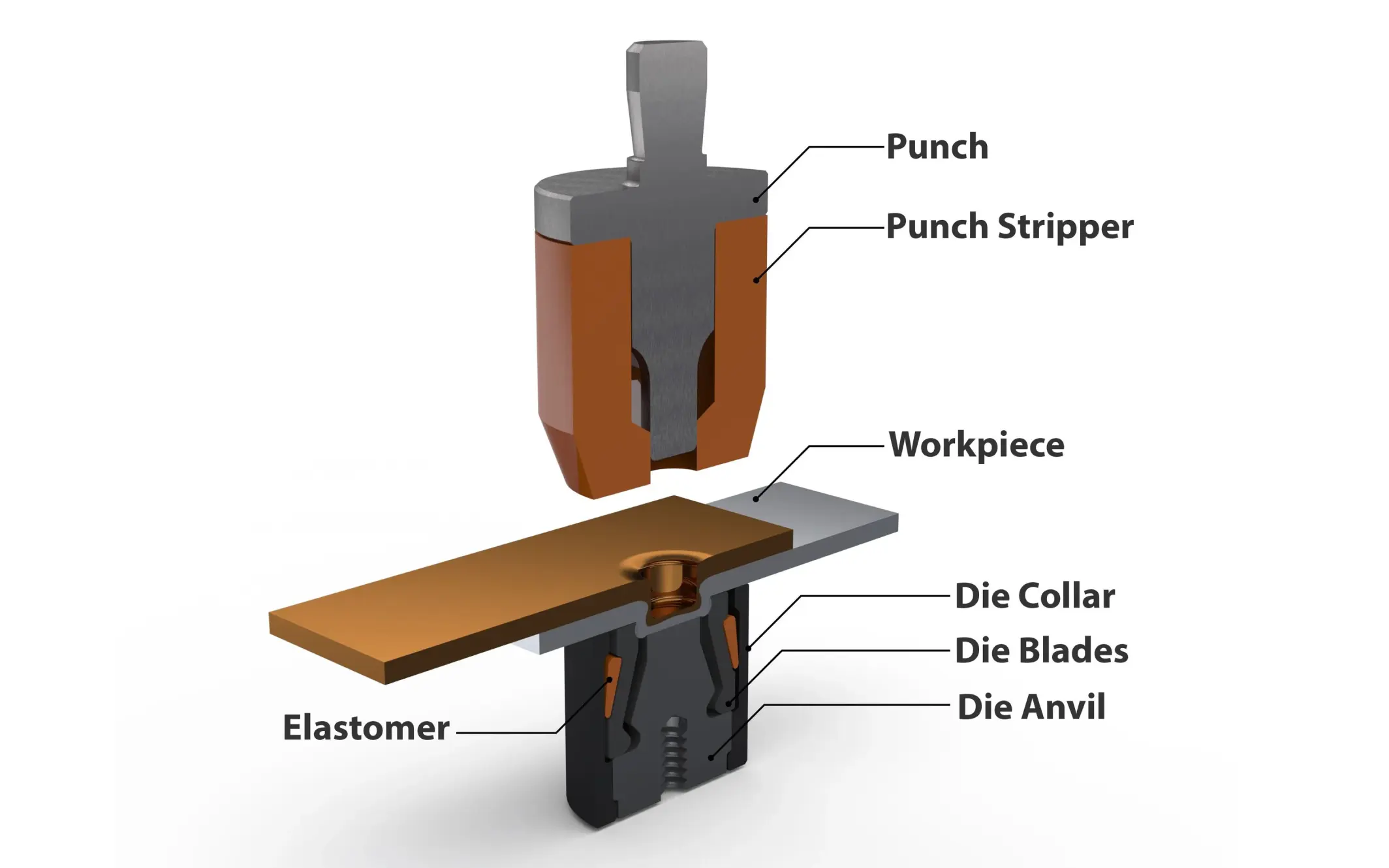
The two types of clinch joint failure
To check our joint, we first need to understand how it could fail. There are two ways clinch joints can fail:
- A pop failure is where the joint pulls apart, leaving a dimple in the metal behind.
- A shear failure happens when the joint leaves behind a hole in the punch side material.
1. The causes of pop and shear failures
Pop failures are often caused by:
- Not enough squeeze. If the system being used has a mechanical adjustment or a pressure switch adjustment, the mechanical stop may be stopping the tooling from traveling as far as necessary and/or the pressure switch could be giving the signal for the tooling to return before full travel has been completed.
- Too low clinching force. In this case, you need to increase the tonnage, so the metal is clinched more securely. This can be as simple as increasing the air regulator pressure on a pneumatic machine.
- Using the incorrect die. The die would be too shallow, so the created clinch joint doesn’t go deep enough into the metal. Here, you need to switch to a die deeper. Go from a 0.040” (1.00mm) deep die up to a 0.050” (1.27mm) deep die.
- Using the incorrect punch. If the punch tip radius (PTR) is too large, the punch won’t form the material outward to create the clinch interlock into the metal. You need to select a sharper punch. Going from, say, a .020” (.50mm) down to a .015” (.38mm).
- Too hard material. If switching out all of the above doesn’t result in an improvement, it could be that the issue is caused by the material itself. Harder or less ductile materials may still be clinchable but would likely need to consider a different style of tooling like square or rectangular, which helps the material “flow.”
Shear failures often have similar but opposite causes:
- Too much squeeze. Opposite to the above, if the mechanical stop or pressure switch allows the tooling to squeeze the material too much, the material will be stretched too thin to have enough strength. Backing off the mechanical stop so that the tooling finishes travel sooner, or reducing the pressure switch to create the Goldilocks zone of “just right” amount of squeeze.
- Using the incorrect die. The problem could be that the die is too deep, so you need a shallower die. For example, go from a 0.050” (1.27mm) deep die to a 0.040” (1.00mm) deep die.
- Using the incorrect punch. If the PTR is too small and, therefore, too sharp for the material, it can create a hole. Increasing the PTR from say .010” (.25mm) to .015” (.38mm) can make a large difference
- Too brittle material. Some materials just aren’t flexible enough to form into a clinch joint. This can also happen if the punch side of the material is too thin compared to the die side material. The 50% rule applies here. If the punch side material is less than 50% of the die side material thickness, clinching can be difficult. You can contact us for help finding solutions.
How to inspect a clinch joint non-destructively
You can test a joint:
- Destructively by pulling it apart.
- Non-destructively by measuring certain parts of the joint.
- Visually by looking at the joint.
With enough experience, a visual inspection can go a long way to ensure your joints are stable. It’s generally a good idea to have a checklist for the operator of the clinching machine to run through at the beginning of every production run.
Since clinching machines are very consistent (if they aren’t, you likely have a functional issue with the machine itself), checking at the beginning will ensure you have the most efficient use of material.
A visual inspection is quite simple. You want to look at:
- The surface of the material and see if there are any gaps or damage.
- How uniform the joint is. You need consistent width and depth for stable joints.
- Any deformation and fracture of the material. In aluminum specifically, cracks in the button cap of the material can be an indication of over clinching, or a material supply issue.
Here’s what a good clinch joint should look like.
Once you have one or two good clinch joints, there are two measurements you can check to replicate that:
- The button diameter (BD) is measured with a caliper or go/no-go gauge. This is the diameter the material has formed to. The measurement can sometimes be tricky since the clinch formed is not a perfectly concentric circle. It is helpful to have visual work instructions for operators to follow. We can help supply that instruction and a caliper.
- The clinch thickness (CT) can be measured with a clinch thickness measuring tool. For round dies, the CT should be about a third, sometimes even a fifth, of the total thickness of the material you’re clinching. For example, if you are clinching two layers of 0.040” (1mm) thick aluminum. A good starting point would be to squeeze the material down to 0.026” (0.67mm) For rectangular tooling, it should be about half of the total thickness, using the same example you would start with 0.040” (1mm) as your target CT. CT is usually very consistent, typically staying within .003” (0.08mm) or less. We also stock clinch thickness measuring tools.
Here’s what measuring those looks like.
Ways to check a clinch joint destructively
If a clinch joint failure could result in a critical problem, lab tests are a good way to ensure the joint’s stability and that you have the right measurements on an ongoing basis.
There are three lab tests you’d have to get done in a workshop. For each of these, you take a piece of material about the size of a business card, clinch it, and then pull it apart.
- A lap shear test involves pulling the sheets of metal apart along the axes.
- A pure tensile test overlaps the two pieces into an x shape and pulls them in the direction of the punch. These are rarely completed due to the complexity in setup at the lab.
- A coach peel test involves folding the material at a 90° angle and pulling it apart.
You’d need to run at least 30 of these tests (if not more) to get enough statistical data that you can rely on. We’re happy to provide tailored advice for your situation.
What’s causing my clinch joint failure?
If you aren’t happy with how your clinch joints are coming out, these are the first questions to ask:
- Have you joined this material with this tooling and machine successfully in the past? A certain amount of trial and error is normal when you’re setting things up for the first time. In that case, just experiment with different dies, punches, and machine settings until you find the right balance.
- If yes, did something change prior to this? For example, maybe a new person operated the machine, or you changed your material supplier. That should help you pinpoint which variable you need to check.
- Can you retest it with a material you know has worked in the past? If it doesn’t work again, you can assume the problem is either the tooling or the machine. If it does, then it’s likely an issue with the material.
Joining metal reliably
Adopting an inspection method and understanding the common causes of joint failures will help you maintain high-quality standards in your cold metal joining processes.
At Press Lock Technologies, we know what it takes to keep production lines running. Check out our clinching machines and clinch tooling here.
.webp)
Take our 5-day course
Get an article every day for 5 days
Don’t have time to read everything now? Sign up and we’ll send you an article every day for 10 days.